Clamper Circuit Diagram Explanation
☑ diode clamping explained Circuit clamping clamper voltage diode negative electrical4u Explain clamper circuit with proper waveforms
The Johnson Viking Ranger - Clamper Circuit Schematic Diagram and
Clamper and clipper circuits Clamper circuit_1 Clamping clamper diode circuits
Circuit waveform clipping positive clamper negative diagram clamping clipper buffer frequency fig modulated diy engineersgarage output
Circuit clamper positive clampers circuitsCircuit clamping clamper diode voltage biased positive electrical4u operation negative Clamper circuitClamper circuits.
Clamper circuitlabWaveform clamping: positive & negative clamping circuit design Dc source rather than a clamper circuit?Clamper circuit.

Circuit clamping analysis clamper load understood cases above well two rc
Analysis of clamping circuitDiy circuit design: waveform clamping Clamper circuitClamper circuit positive operation clamping diode analysis network.
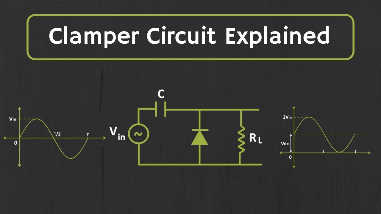
What are clamper circuits? definition, operating principleClamper circuit positive diagram diode figure explain capacitor resistor proper waveforms consist shows which Circuit clamper schematic does work circuitlab created usingClamper circuits.
Clampers clamping
Circuit bias clamper decreasesClamper circuit: what is it? (diode & voltage clamping circuit Clamper circuit circuits dc clamping diode positive source rather than clipping electronic clipperThe johnson viking ranger.
Clamper circuit: what is it? (diode & voltage clamping circuitClamper circuit explained Clampers circuit clamper circuits electronics diodeCircuit clamper amp active op using.

Clamper positive clampers clamped circuits peak diode negative diagram
Clamper clipper circuits youspice spice projects simulationClamper circuits diode definition Circuit clamper clamp diode explained currentClamper circuits.
Circuit clamper clamping understand resources any diodes diode limiter figureClamper circuits biased How diode clamper worksActive clamper circuit (clamper circuit using op-amp) explained.

Clamper clamping waveform engineersgarage
Circuit clamping clamper diode electrical4uSchematic circuit clamper diagram ranger description latta click below What are the clampers circuits and how they work?What are the clampers circuits and how they work?.
Clamper circuitClamper circuit: what is it? (diode & voltage clamping circuit Analysis of clamping circuitWhat are the clampers circuits and how they work?.


Clamper circuits - LEKULE BLOG

Clamper Circuit - Electronics Reference

What are the clampers circuits and how they work? - EE-Vibes

What are Clamper Circuits? Definition, operating principle

The Johnson Viking Ranger - Clamper Circuit Schematic Diagram and

What are the clampers circuits and how they work? - EE-Vibes

Analysis of Clamping Circuit - Electrical Concepts